ESP32 DevKit is fried when powered externally.
-
- Posts: 5
- Joined: Tue Oct 24, 2023 5:28 pm
ESP32 DevKit is fried when powered externally.
Hello All,
I am a hobbyist and trying to making a gardening system with ESP32 DevKit. I have connected 12V DC adapter to LM2596 to convert it to a 5V and then it is connected to the VIN of the ESP32 Dev Kit. It works for sometime ( May be couple of hours)but not more than 3 or 4 hours. It got fried after that . I have ensured that the voltage is 5V at the output LM2596 while connecting it but not sure what happened. When it is powered on now (after fried), it is getting extremely hot within few seconds. The code is very simple Blynk app to turn a relay on for few seconds in every X minutes.The relay is connected to an solenoid valve that regulates the water. I am not sure what is causing it to fry ESP32 dev kit. During some google search, one of the post in this forum was mentioning about adding capacitors after LM2596. I am uncertain whether this is the issue or something else. Could any of you please help me to understand what should I do to prevent frying new ESP32 dev kits?
The block diagram is given here for your reference.
- Attachments
-
- ESP32_Block_Diagram.png (9.74 KiB) Viewed 5468 times
-
- Posts: 9761
- Joined: Thu Nov 26, 2015 4:08 am
Re: ESP32 DevKit is fried when powered externally.
What relay did you use and how did you connect it?
-
- Posts: 5
- Joined: Tue Oct 24, 2023 5:28 pm
Re: ESP32 DevKit is fried when powered externally.
Hello,
Please find the full connection diagram
.
The relay is a normal 2 channel relay board is what I have used. Link is provided for reference :
https://robu.in/product/2-channel-isola ... 1MQAvD_BwE
Please find the full connection diagram
.
The relay is a normal 2 channel relay board is what I have used. Link is provided for reference :
https://robu.in/product/2-channel-isola ... 1MQAvD_BwE
- Attachments
-
- ESP32_Block_Diagram.png (19.51 KiB) Viewed 5406 times
Re: ESP32 DevKit is fried when powered externally.
You could mess about two different things in your design:
1. The most of dev boards have USB powering source which is 5V. But, on those boards there is 5V->3.3V converter because ESP32 uses 3.3V voltage. So if you bring your 5V to the USB input its ok. However, if you connected your 5V after 3.3V converter direct to ESP32 that can fry a chip after some time.
2. Most of relays consume large amount of current. Order of magnitude larger in comparison to LED. ESP32 (in general, the most of microcontrollers) can not provide that. So you need, lets say a N-MOSFET transistor whose gate can be triggered by small amount of current provided by pad on ESP32 chip. Then, you should know required voltage for that relay for its proper operation. It could be 12V it could be 5V it could be anything in between....it could be even smaller value. Depending on that information, source pin of that N-MOSFET will be connected to proper + voltage, drain pin of that N-MOSFET will be connected to plus pole of your relay and finally minus pole of your relay will be connected to ground (minus side of your 12V DC adapter). That way N-MOSFET provides a current for your relay. To pick a proper mosfet you have to know operational voltage of your relay and maximal current it can suck on that voltage. If you do not have those parameters you can measure (by an amp meter) connected in series with your relay and voltage source. For example if relay works on 5V you will hear "click" once you connect it direct on 5V. Then you add amp meter in series and measure the current. Then multiply that value by lets say 4. You need a mosfet capable to hold somewhat larger current because of reverse currents due to self-inductance on transitional states. So for larger inductive loads there are mosfets with integrated reverse diode to prevent those currents affect the other sensitive electrical components like ICs.
-
- Posts: 5
- Joined: Tue Oct 24, 2023 5:28 pm
Re: ESP32 DevKit is fried when powered externally.
Thank you for your suggestions.
Kindly let me know if I misunderstood something here.
Thanks in advance.
Kindly guide me here, my understanding is VIN pin on ESP32 accepts 5V and still goes through the voltage regulator. Isnt it the case?The most of dev boards have USB powering source which is 5V. But, on those boards there is 5V->3.3V converter because ESP32 uses 3.3V voltage.
I seek the guidance here. The 5V relay is powered from the LM2596. The ESP2's GPIO is the pin that is connected to the relay board's input pin, I am assuming the current consumption does not happen from ESP32. The other question that I have is, typically these relays are mentioned as optocoupler relays. I am assuming it requires only small amount of current to turn on the opto coupler from the ESP32 pin.Most of relays consume large amount of current. Order of magnitude larger in comparison to LED. ESP32 (in general, the most of microcontrollers) can not provide that. So you need, lets say a N-MOSFET transistor whose gate can be triggered by small amount of current provided by pad on ESP32 chip.
Kindly let me know if I misunderstood something here.
Thanks in advance.
Re: ESP32 DevKit is fried when powered externally.
In that updated schematic (it is still not clear of how those both red and green lines, entering relay(s), connected internally in relay(s). Solenoid in a single relay is just two pole "wire" and when it is connected into closed circuit with a switch it is connected in series. So one of those two wire is not required unless that relay module contains some electronic in it. However, it is also possible that you made a mistake by connecting two solenoids of both channels in series "through" ESP pads which then explains why it is fried )))).
Anyway, you can remove the relay(s) and use N MOSFETS as a replacement.
1. Source (pin) of mosfet connect to +12V,
2. Drain (pin) of N Mosfet connect to + of your solenoid valve (keep minus pole from a valve to GND)
3. Gate (pin) of N Mosfet connect to pad of your ESP32 via lets say 10 ohm resistor
that green line is not required in that case.
According to that scheme and diode 4007, current is not more than 2A at 12V, so any standard N mosfet capable of holding lets say 10A on 30V (it costs about 0.1 $) will do the job.
Also ensure that all GNDs of all your sources are tight together.
(if you need another channel you will need to spend another 0.1 $ for one more Mosfet transistor)
However, if you insist on keeping those relay(s) (it has sense only if in the future you decide to use larger load, lets say something which works at 220V instead 12V valve) you have to provide those internal connections inside relays if there is some electronics. However, if you made a mistake by connecting two solenoids in series like on that schematic then:
1. Remove the green wire (it is not required until you utilize second channel) and remove +5V wire entering relay(s)
2. Disconnect both pads from relays
3. Connect source (pin) of mosfet to +5V
4. Connect gate (pin) of mosfet via 10 ohm resistor to pad (of first channel)
5. Connect drain (pin) of mosfet to most upper pin on relay module on that schematic (one pole of first solenoid)
6. Connect another pole of that solenoid to the GND
(both poles of second solenoid should be free at that moment)
If you want to utilize second channel use one more mosfet and repeat steps 3-6 but using second channel from ESP and free solenoid in relay module.
Re: ESP32 DevKit is fried when powered externally.
hi
I recommend connecting power
VCC -> 3.3 V ( ESP32 Devkit 3.3 out )
JD-VCC -> 5 V
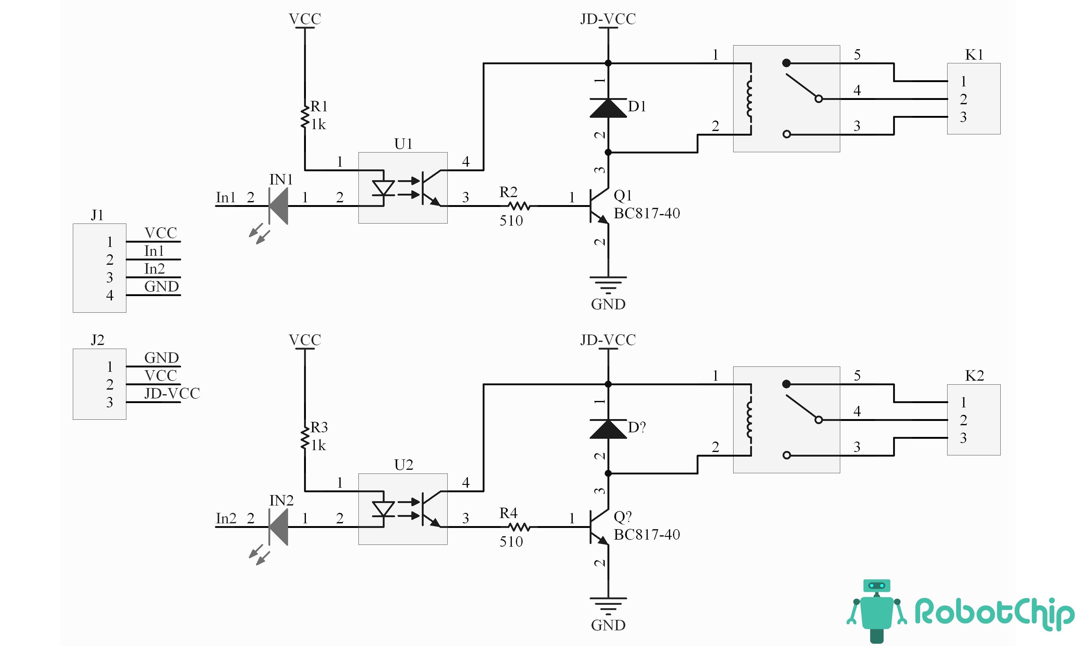
Below is a diagram of this relay block
I recommend connecting power
VCC -> 3.3 V ( ESP32 Devkit 3.3 out )
JD-VCC -> 5 V
Below is a diagram of this relay block
-
- Posts: 5
- Joined: Tue Oct 24, 2023 5:28 pm
Re: ESP32 DevKit is fried when powered externally.
Thank you ok-home & djixon for your support.
Assume I take the route with relays, this is the relay board that I am using.
I am assuming the components that ok-home suggested is inbuilt into this circuit.
Kindly correct otherwise.
Assume I take the route with relays, this is the relay board that I am using.
I am assuming the components that ok-home suggested is inbuilt into this circuit.
Kindly correct otherwise.
- Attachments
-
- 2-channel-5v-optoisolated-relay-module-1.jpg (81.96 KiB) Viewed 5272 times
Re: ESP32 DevKit is fried when powered externally.
is very similarI am assuming the components that ok-home suggested is inbuilt into this circuit.
Kindly correct otherwise.
-
- Posts: 5
- Joined: Tue Oct 24, 2023 5:28 pm
Re: ESP32 DevKit is fried when powered externally.
I am using similar relay board as I mentioned in the first post. Now I am thinking of a couple of things.
1.I have not grounded 12V (DC adapter) and from 5 V (Buck converter). Do I need to ground both of them ?
2. I have put everything into a box. May be there is no enough ventilation and it get overheated . Probably I shall change the enclosure if there are no problems with the circuit.
3.Do I need to add any capacitor after the 5V ? (Due to some ripple effect or something ?)
Any other thoughts?
Who is online
Users browsing this forum: Bing [Bot] and 48 guests