
I've built a monitor for our dual sump pump system and need to obtain the voltage from the 12 volt deep cycle battery. I made a voltage divider using 13k and 3.2k resistors. I took seven readings across the voltage divider without any other components attached, from 9 to 15 volts. The outcome was as I expected, with each millivolt reading from pin 0 increasing .195 millivolts from one input volt to the next.
When I incorporated the voltage divider into the project, however, the readings from the voltage divider where no longer linear.
Volts Pin 0 Millivolts
15 2923
160
14 2763
124
13 2639
114
12 2525
101
11 2424
100
10 2324
97
9 2227
As you can see from the readings, the difference from one volt to the next increases as the voltage rises. I'm new to the ESP32 microcontroller and I'm not familiar with whatever quirks it might have. Can anyone point me towards something to look at?
Thanks!
Voltage divider / Non linear output
Re: Voltage divider / Non linear output
ESP32 is well known for its ADC issues, including noise, incomplete range and NON-LINEARITY which you are asking about.
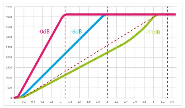
If you can see the image above, you will see why you have the problem.
The ESP32 ADC has an internal voltage reference of around 1.1V (which varies slightly between each chip).
In order for you to measure the input voltage of up to 3.3V, there is an internal voltage divider or attenuator.
Without the attenuator, your ADC could only read up to about 1V.
With the default attenuation of 11dB, such as in your case, you can TECHNICALLY read up to 3.3V, BUT in reality you can't read more than about 3.10V or less than about 0.15V, due to the non-linearity of both the ADC and the attenuator which apparently INCREASES this non-linearity.
Even the Espressif documentation specifies "preferred" voltage range, meaning the useful and linear part of the ADC input voltage:
Attenuation - Preferred voltage range
ADC_ATTEN_DB_0 - 100mV~950mV
ADC_ATTEN_DB_2_5 - 100mV~1250mV
ADC_ATTEN_DB_6 - 150mV~1750mV
ADC_ATTEN_DB_11 - 150mV~2450mV
As you can see from all of the above, as your voltage increases above 2.4V on the ADC input, which happens around 12V on your battery, the results start becoming increasingly larger (although it's not great even below that point).
There are a few, relatively complex ways to fix the problem, including polynomial calculations included in your code, but I will suggest the simplest solution to your problem:
increase the ratio of your resistors, so that the highest voltage you want to measure produces no more than 2.4V at the ADC input.
Just use an 18k resistor instead of the 13k one. You could also increase the overall resistance of your resistive divider since the ADC doesn't need that much current.
To reduce the noise in your readings, you could place a 1-10uF capacitor between the ADC input pin and the ground nearest to the MCU.
Last edited by EdinF. on Mon Feb 12, 2024 8:59 pm, edited 1 time in total.
Re: Voltage divider / Non linear output
One RSP32 "quirk" is that the ADC is not the best. If 12 bit accuracy is required an external ADC is what some are using. Or a different micro-controller.
A bunch of threads discussing this issue on this and other forums can be found with a search.
A bunch of threads discussing this issue on this and other forums can be found with a search.
Old controls guy, SW Ontario, Canada .
-
MicroController
- Posts: 1389
- Joined: Mon Oct 17, 2022 7:38 pm
- Location: Europe, Germany
Re: Voltage divider / Non linear output
Try calibrating the ADC and see if things improve.
Re: Voltage divider / Non linear output
Thanks gang! After doing more research and experimentation, I've decided to go with an external ADC. I ran the same experiment with Arduino Uno and Mega 2560 boards, and they were both quite accurate. The values returned were linear as the voltage increased. This project doesn't require a high level of granularity. A reading to the tenth of a volt is sufficient. It's just monitoring a deep cycle battery on our sump pump when the AC power is out.
Re: Voltage divider / Non linear output
Thanks Edin. I had the same thought while driving to my sister in laws for the super bowl. I noted values from 1 to 15 volts & noticed the results were pretty linear when the input voltage was less than 8 or 9 volts. I'll do further experimentation tomorrow morning & will post the results.
Re: Voltage divider / Non linear output
You're welcome!
If you already need ESP32 for its communication and processing capabilities AND your ADC doesn't need that much resolution, you should be just fine staying with ESP32 ADC - all you need to do is increase the voltage divider ratio so that the range you need is included in the linear portion of the ADC response and maybe include some code to reduce noise if necessary. You can also specify a lower resolution for the ADC (like 10 or 11 bits) or simply use no more than 2 or 3 digits after decimal point; the fourth one is the most noisy one anyway.
If you already need ESP32 for its communication and processing capabilities AND your ADC doesn't need that much resolution, you should be just fine staying with ESP32 ADC - all you need to do is increase the voltage divider ratio so that the range you need is included in the linear portion of the ADC response and maybe include some code to reduce noise if necessary. You can also specify a lower resolution for the ADC (like 10 or 11 bits) or simply use no more than 2 or 3 digits after decimal point; the fourth one is the most noisy one anyway.
Re: Voltage divider / Non linear output
The 3 pack of ADS1115's arrived today & they're spot on! Looking forward to finishing this project & moving on to others. Thanks again for the responses. They confirmed what I was suspecting.
Who is online
Users browsing this forum: axellin and 64 guests