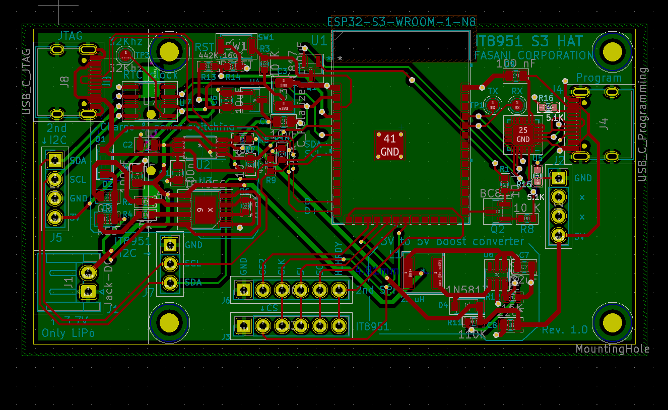
ESP32S3 PCB design with 2 USB-C
Posted: Tue Jun 14, 2022 8:29 am
Hi there board,
I'm designing a S3 SPI master board, that will feed some IT8951 with pixel data for some 9.7 epaper displays.
Schematics: https://github.com/martinberlin/H-cinre ... ematic.pdf
It has 2 USB-C's:
1 is for programming using USB - UART using CP2102
2 is for JTAG debugging
A good soul indicated me that CC* (Configuration mode) need 5.1K pull-down resistors.
My question is: Do also JTAG USB need this?
And also to enter USB debug mode does the board need to be in DFU Mode?
If that is a YES then I should add a second BOOT button since you need to press BOOT + RST in order to see the board being identified in the list usb.
Other than that if there is any interesting review here is how the PCB looks:

